
Saturday, November 10, 2012
Saturday, October 13, 2012

Monday, September 24, 2012
PSK vs. FSK/MSK
In thinking about BPSK vs. FSK or more accurately, MSK (Minimum Shift Keying) I found myself pondering whether they are functionally equivalent.
MSK is basically FSK with the shift set to ½ the baud rate. Realistically this is the smallest shift you can use without trading off transmission speed. At 31.25 baud in MSK your keying frequency shifts are 7.8125 either side of your transmit center frequency. If you think of the phase of a carrier that is 7.8125 below the transmit center frequency, it will lag by 90 degrees after 32 mS, and at 7.1825 above, it will lead by 90 degrees after 32 mS, so MSK appears to be functionally equivalent to BPSK while using +90 and -90 degree shifts instead of 0 and 180.
I like MSK/FSK when it comes to transmittter design as there is no amplitude modulated component to the signal, greatly simplifying transmitter design as non-linear techniques can be utilized. I wonder however if there is a price to be paid on the receiver side when trying to decode the signal at low signal levels and in trying to keep simple receiver designs locked onto the signal.
MSK is basically FSK with the shift set to ½ the baud rate. Realistically this is the smallest shift you can use without trading off transmission speed. At 31.25 baud in MSK your keying frequency shifts are 7.8125 either side of your transmit center frequency. If you think of the phase of a carrier that is 7.8125 below the transmit center frequency, it will lag by 90 degrees after 32 mS, and at 7.1825 above, it will lead by 90 degrees after 32 mS, so MSK appears to be functionally equivalent to BPSK while using +90 and -90 degree shifts instead of 0 and 180.
Sunday, September 16, 2012
Propeller PSK31 - Updated
Working on PSK31 encoder that will eventually become part of a new beacon mode for my set of Propeller beacons.
PSK31 is a digital communications mode which is intended for live keyboard-to-keyboard conversations, similar to radioteletype. The data rate is 31.25 baud (about 50 word-per-minute). PSK31's ITU emission designator is 60H0J2B. It uses BPSK modulation without error correction.
Instead of traditional frequency-shift keying, the information is transmitted by patterns of polarity-reversals (sometimes called 180-degree phase shifts). One way to think about this would be to swap antenna terminals on each phase reversal.
The 31.25 baud data rate was chosen so that the system will handle hand-sent typed text easily. There is a problem with PSK keying, namely the effect of key-clicks. If hard keying of phase reversals were done, the result would be a very broad emission. The solution is to filter the output or to shape the envelope amplitude of each bit, which amounts to the same thing.
In PSK31 a cosine shape is used. Phase reversals are done at the minimum amplitude points. The spectrum during a continuous sequence of polarity reversals at 31 baud will consist of two pure tones at +15/-15 Hz from the center frequency and no splatter. A binary 0 is represented by a phase reversal and a binary 1 by no phase reversal.

My initial implementation will be to generate PSK at audio frequencies and later to investigate strategies to generate at RF frequencies. The audio tone chosen is 1 KHz constructed from 32 eight-bit samples at full amplitude per cycle. The period of a 1 KHz tone cycle is 1 millisecond. Each of the 32 samples per cycle has a period of 31.25 microseconds. The audio samples are eight bit values from $00 - $FF with the zero crossing value at the midpoint $80.
The PSK31 character bit time is 32 ms constructed of 1024 samples. A binary zero is represented by a phase reversal while a binary one is presented by the absence of a phase reversal. Characters are encoded with a variable bit length code (varicode) where the length of each character is inversely proportional to the frequency of use. Characters are encoded with a bit pattern where there are no sequential zero bits. Two zero bits in a row signify the end of a character.
In order to implement the ramp up/down scenarios at phase reversals, I have constructed a couple of tables of sinusoid information. The first consists of 512 table entries defining the 16 cycles of ramping up from zero to full amplitude. I have plotted the data in Excel as follows:

Once I get up to full amplitude, I use a separate 32 eight-byte table consisting of a single sinusoid. For a binary zero, I ramp down (512 samples) by processing the above table in reverse, reverse the phase and immediately ramp back up again (another 512 samples), this time processing the table in the forward direction. For a binary one, I use the 32 eight bit sample table below and repeat it 32 times for 1024 total samples.

The PSK31 engine is a PASM module that runs continuously in its own cog. Once started, it will begin playing a series of double zeros (continuous phase reversals) indicating there is no data to send until the cog is stopped or a data string is passed to it. A string buffer is passed to the cog with the first four bytes containing the length of the string, the data bytes following immediately.
The audio output is generated using PWM generated from the cog's counter in Duty mode. The zero crossing point is represented by a 50% duty cycle. A simple RC low pass filter is used to clean up the audio before amplification. Alternatively an external operational amplifier could be used to accomplish the same task. I am using a Propeller demo board which has a nice fixed gain stereo headset amplifier connected to pins 10 and 11 of the Propeller board. This configuration works quite nicely. Here is a partial schematic showing this setup:

I have completed the PSK engine with the exeption of the ability to pass in a string to send. For now I have hard coded a CQ message for testing purposes. I have been able to decode the audio using several PSK applications on both Windows and Macintosh platforms. A little more code and I think this little beacon will be ready to integrate with my collection of other beacons. I have implemented a $00 - $7F varicode table to translate ASCII characters into varicode before transmission.
Next I hope to investigate the possibility of implementing an RF solution rather than an audio solution.
Saturday, August 25, 2012
Sunday, August 19, 2012
Hey! Remember me?
Wow, it sure has been a long time since I posted anything. Been buried at work and allowed myself to get too sucked into a mode where I worked 7 to midnight and then crashed for a few hours before starting it all over again. Well, things have got to slow down for me as I can't keep up any more. Making too many mistakes that I can't afford.
So, I took the weekend off and spent most of it sleeping. Tried to get the plane out and do some flying, but I just didn't feel like I had gotten sufficient rest to be safe about it, so the cub stayed in the hanger. Maybe next weekend.
I have to dig out the shack and un-bury it from all the crap that has stacked up around me. Hopefully I can get back to building things again.
Friday, May 18, 2012
Guess what arrives in the post?
Yep, that's right folks... KX3 serial number 160 was placed on the porch last evening without so much as a signature. Glad it came before Salmoncon 2012 later this summer as I was hoping to have it on hand for that outing and hopefully a SOTA activation during that event.

Opening the box we find an accessories tray with power cord, USB cable, CW paddles, allen wrenches and so forth. Elecraft does a nice job packing things up for shipment. In one of the envelopes was a "Packed with care by Stephanie" slip. :) Thanks Stephanie!
 Next layer down, we find the microphone and the KX3 itself.

Carefully wrapped in a plastic bag as well as bubble wrap, surrounded by cardboard spacers was the KX3.

As they say on the EEVBlog, "Don't turn it on! Take it apart!" Here we can see the soul of the machine and a pile of AA cells later, we fired 'er up! I love how it comes up on all the QRP CW frequencies out-of-box.


Spent a little time just tinkering with the receiver last evening. This is one sweet ride of a CW rig. Today hooked up the paddles and spent some time adjusting them and practicing with the sidetone only. Hope to put it up on the air sometime this evening or this weekend at the latest.

Opening the box we find an accessories tray with power cord, USB cable, CW paddles, allen wrenches and so forth. Elecraft does a nice job packing things up for shipment. In one of the envelopes was a "Packed with care by Stephanie" slip. :) Thanks Stephanie!


Carefully wrapped in a plastic bag as well as bubble wrap, surrounded by cardboard spacers was the KX3.

As they say on the EEVBlog, "Don't turn it on! Take it apart!" Here we can see the soul of the machine and a pile of AA cells later, we fired 'er up! I love how it comes up on all the QRP CW frequencies out-of-box.


Spent a little time just tinkering with the receiver last evening. This is one sweet ride of a CW rig. Today hooked up the paddles and spent some time adjusting them and practicing with the sidetone only. Hope to put it up on the air sometime this evening or this weekend at the latest.
Thursday, May 3, 2012
Off to 4-land today
I am off today to Orlando for a quick visit to my son who is graduating college. Whoo hoo!
Wednesday, May 2, 2012
WWVB anyone?
When I arrived back from Finland, I had a little package waiting for me that contained this:

This is a 60 KHz WWVB time receiver module and the associated loop antenna. I plan to play around with this as an alternative time source to a GPS receiver for syncing beacon signals such as is needed with WSPR. This was obtained from the good folks at PV Electronics in the UK. If anyone has any experience with these modules, I would appreciate any insights as I am going at it totally cold.

This is a 60 KHz WWVB time receiver module and the associated loop antenna. I plan to play around with this as an alternative time source to a GPS receiver for syncing beacon signals such as is needed with WSPR. This was obtained from the good folks at PV Electronics in the UK. If anyone has any experience with these modules, I would appreciate any insights as I am going at it totally cold.
Tuesday, May 1, 2012
Back in W/K/N-land
I arrived back in the US after a great trip to Finland. Next trip will include either the KX1 or the KX3 (if it ever comes...) :)
I got to do a bit of SWLing but had nothing with which to transmit. Probably ok given my 18 hour day work schedule.
I am off to Florida Thursday for my son's college graduation and then travel should slow down for a bit.
Jet lagged in Seattle...
I got to do a bit of SWLing but had nothing with which to transmit. Probably ok given my 18 hour day work schedule.
I am off to Florida Thursday for my son's college graduation and then travel should slow down for a bit.
Jet lagged in Seattle...
Wednesday, April 25, 2012
Finland SWLing
I moved my base of operations today north to Tampere, Finland where I will be the rest of the week. I am having fun SWLing on the ham bands hearing all the call signs I drool over working from the states like they are next door... Because they are! Hanging out on the low end of 20 metres mostly, but I am hearing a lot of activity on 17 metres as well.
Not much antenna to work with (about 8-10 metres of wire) but having fun in OH-land. I will be sure to bring along a QRP rig next time I come to Europe and give those fun airport security folks something to quiz me about.
Not much antenna to work with (about 8-10 metres of wire) but having fun in OH-land. I will be sure to bring along a QRP rig next time I come to Europe and give those fun airport security folks something to quiz me about.
Monday, April 23, 2012
Greetings from Finland
I arrived today in Finland where I will be working this week. I brought along a little Grundig G6 Aviator receiver (yeah, it's the "Buzz Aldrin Edition") as it is tiny, runs on batteries and also has a BFO so I can decode CW and SSB signals. I have a little wire antenna I clip on the whip and string it up in the window of my hotel. 20 metres is very busy tonight with a lot of CW, digital and SSB signals. It will be interesting to see how the band does as the sun goes down. Only problem is... I can barely keep my eyes open as I have been up for about 24 hours. We shall see how it goes.
Thursday, April 19, 2012
Off to OH-land (Finland)
This weekend, I will be traveling to Helsinki, Finland for a week. I have not had time to comply with the Finish Communications Regulatory Authority requirements to apply for a visitor amateur license, so I will not be on the air. I expect that I will be making future trips to Finland, so I will apply for a visitor license when I return. The Finnish Amateur Radio League can be found here.
Thursday, April 12, 2012
Propeller Case
I picked up a nice little lucite (I think) case for my propeller USB proto board. Parallax has them in four colours, clear, opaque red, transparent blue and opaque black. It is simple "tab and slot" construction and goes together easily. It supports the proto board, super carrier board and both the USB and Serial versions of the board of education. Very nicely done. Someone thought this out very well.


Saturday, April 7, 2012
More propeller keyer work
I decided this evening to put a little more work into the propeller keyer. I have added a keyboard interface to it. If your propeller board supports a PS/2 keyboard, you can set the keyer mode to keyerModeKBD and it will use the keyboard for input rather than the paddles. A typical keyboard interface would look like this:

The clock is wired to pin 27 and the data to pin 26, to allow the standard keyboard library to be used.
Realistically speaking, it is difficult to type blind on a keyboard, especially when you can type faster than the morse code is sending without visual feedback as to what you are typing. It would be more realistic to implement some sort of LCD display to show keyboard input, allow backspacing, while the keyer is sending the buffer. However, I have not yet implemented those components though I have all the necessary pieces.
I took the morse code tables from my QRSS beacon and added all the defined punctuation characters so as to have a complete implementation. I will be sharing a new version on github as soon as I have the code completed and tested sufficiently.
I have implemented the ability to change the morse code send speed from the keyboard. The up/down arrows change the speed by 1 WPM whilst the left/right arrows change the speed by 5 WPM range limited for 5 WPM to 60 WPM.
I plan to add memories for canned messages that can be sent with a function key press stored in EEPROM which will include serial/sequence number substitution for contest work.
Wow... Nice day...
One of those beautiful days in the Northwest that makes up for all the rainy, foggy, overcast days. Mid-60's and clear. Spent the day flying the cub and hanging out at airports. It is the kind of day that brings a lot of folks out to enjoy the weather.
Ran across this little gem today in the Dairy Queen parking lot. Pretty cool, huh?

Ran across this little gem today in the Dairy Queen parking lot. Pretty cool, huh?

Thursday, April 5, 2012
Stable Propeller Clock
Well, I obtained a nice temperature compensated 10 MHz clock for my propeller board, courtesy of Eldon WA0UWH. Here you can see the little daughter board that Eldon designed. The normal 5 Mhz crystal has been removed and the software adjusted to set the system clock at times 8 instead of times 16, so we are still running at 80 MHz.

After spotting it on 10.140.200 MHz I captured my WSPR decode and as you can see in the last spot after touching up the pot a little, I am spot on frequency (10.140.200) and zero drift. Yeah! The waterfall display shows me swinging the pot through its range over several samples.

The board has a nice, though a little touchy pot to net the frequency where you want it. It currently has a range of about 100 Hz. In the final version, I think this will be tweaked to slow the tuning down to about 1/2 that amout or so. Once adjusted it stays put and doesn't seem to be affected by temperature as expected.
The oscillator output looks like this:

So, I am quite pleased with this little modification to the propeller proto board.
Monday, April 2, 2012
April tom-foolery
Wow, I am usually pretty savvy about April fools jokes, but this year I have been completely taken in on several accounts including Eldon's post about his multi-bazillion mile-per-watt QRSS contacts. The only thing I was going to challenge him on was his math... Oh sigh... Not bad enough I was taken in, but he had to name me in his post as though I was somehow a part of it. Nice... I guess I should probably get my spectrum analyzer back before I plot any kind of revenge, eh? :)
Thursday, March 22, 2012
KO7M QRSS Grabber is online
I have put up a QRSS grabber in Redmond, WA for those QRSS fans out there that would like to see how they are doing getting into this part of the world.
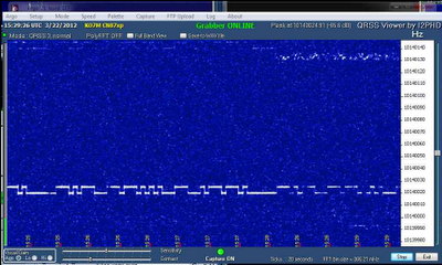
The grabber will be online most of the time except when I decide to grab the 7200 for other purposes. It can be found at http://www.qsl.net/k/ko7m//grabber/. My pal Eldon has his grabber back online now as well. He is about 35 miles north of my location.
The grabber will be online most of the time except when I decide to grab the 7200 for other purposes. It can be found at http://www.qsl.net/k/ko7m//grabber/. My pal Eldon has his grabber back online now as well. He is about 35 miles north of my location.
Sunday, March 18, 2012
Satellite Tracking with Propeller (cont)
Well, I am going to set this aside for a little while and do other things as I am a bit tired of the project. I calculated a perigee pass for AO-51 at .02 km. Hmmm... I am thinking that at less than 70 feet, that might be a little low, eh? :) Ah well... Obviously I have work to do. But, for now this one is shelved and I will come back to it when more refreshed.
Satellite Tracking with Propeller (cont.)
Good progress today. I am actually down to the place where I am debugging the SGP4 implementation. I have initially hardwired the observer's position to be the lat/lon for my home QTH. I also do not handle deep space objects or deal with geostationary objects yet.
All the pre-calc work is done and the SGP4 calculations have completed. The post processing code has some problems that I am working on, but now it is time for sleep.
All the pre-calc work is done and the SGP4 calculations have completed. The post processing code has some problems that I am working on, but now it is time for sleep.
Friday, March 16, 2012
Satellite Tracking with Propeller
Work continues to build a SGP4 object implementation on propeller. Getting the mathematical expressions correct is at best painful. I have been converting a C language implementation into spin little by little. I have written some utilities to assist with that conversion and progress is more quick now and less error prone (I hope). I use the FPU utilities provided to convert the math expressions into FPU assembly language and then run through my utility to convert that to spin.
I could really use some insights into how to validate the results. I can of course always compare results against the version I am converting from, but who is to say that it is correct? Ideally there would be a standard test kep set and a standard observation location that would create known results that could be validated.
The SGP4/SDP4 specification does speak to this a bit, but my understanding of it is not yet adequate to evaluate. If anyone has insights here, I could use some advice.
Wednesday, March 14, 2012
KO7M goes multi-propeller
Well, I have gone to multiple propellers. Good thing I have a multi-engine rating.
I have been working on implementing satellite tracking algorithms (SGP4) on the propeller device as previously posted. I now have a new propeller board that I will be using to drive az/el servos to move an antenna in sync with a satellite pass. This little board can be used drive up to 16 servo motors. If you need more than this, you can daisy-chain two of them together and control up to 32 servos. (I foresee an atonomous flying vehicle in my future, but that is another post for another day...)

I am working with small hobby servos that are capable of moving up to 8 lb of antenna hardware. The pan mount can take 150 lb on top of the mount and 200 lb of side load at the shaft. The tilt mount can handle 8 lb of load.

This is sufficient for my small arrow antenna which is only 20 oz and is giving me some experience in driving servo motors. I could also velcro my solar panel array to it and have it track the sun to recharge my batteries whilst operating off the grid. The pan mount can rotate up to 450 degrees while the tilt mount can rotate 135 degrees. So, this should be fun for some garden experiments with satellites as well as making a fun pan/tilt camera mount.
Future projects of course will scale this up to handle large antenna arrays.
Monday, March 12, 2012
Propeller Receiver
With the success I had with my first propeller receiver I decided to put together a little single conversion superhetrodyne receiver kit from N3ZI for round two. This is a nice little kit and as my buddy Eldon says, makes a nice companion for the propeller board as a transmitter.

Thus far, I have gotten the receiver to pick up some birdies, but have not heard any actual signals through it. The crystal filter appears to be doing its thing as I am getting about 300 Hz to 3000 Hz passing through it with nice roll-off on the top and bottom ends.
Using the propeller as a local oscillator, I am able to tune the device, but I just don't hear anything other than what sounds like birdies. If I set the propeller to the IF frequency, I get a very strong tone. So, everything downstream of the first mixer appears to be working as expected. But for whatever reason, I don't get any off-the-air signals through it.
I will use another propeller device to inject a signal other than at the IF frequency into the front-end and see if I can hear it. That will have to wait for another day however as I am quite fatigued tonight.
Sunday, March 11, 2012
Parsing Keplerian Elements with uM-FPU
Today I played around with my new floating point coprocessor. I decided to build a bit of code that would parse a two line Keplerian Elements.
I have built an object that will parse this data out into its constituent values using the coprocessor. The output from this test looks like this:
AO-51
1 28375U 04025K 12068.46137681 +.00000200 +00000-0 +72724-4 0 02147
2 28375 098.1341 038.4897 0084202 346.8009 013.0981 14.40905486404267
satName: AO-51
idesg: 04025K
epoch: 12068.46
xndt2o: 1.9999999E-6
xndd6o: 0.0
bstar: 7.2723999E-5
xincl: 98.134101
xnodeo: 8.4897
eo: 0.0084201993
omegao: 346.8009
xmo: 13.098098
xno: 14.409052
catnr: 2837
wlset: 0.0
revnum: 40426
It is interesting to note the effect of a 32 bit floating point value used to hold this data. Since only 7.2 significant digits are available, values like epoch have been truncated to fit in 32 bits. I parse out 12068.46 for a value that should be 12068.46137681.
At best only an approximation is going to be possible with 32 bits for SGP4 calculations, which given the beamwidth of my antennas is likely to be sufficient. In any event is is an interesting chip to work with.
With 128 floating point registers available and the ability to store user-defined functions on-chip, I am hopeful that the calculations can be done completely on-chip. In an ideal world, I would pass in the kep of the satellite of interest as a string and would get back azimuth, elevation, aquisition/loss of signal times, etc. In a more ideal world, I would get back only the necessary information to move an az/el rotor system to the correct point in space. We shall see how it goes...
I have built an object that will parse this data out into its constituent values using the coprocessor. The output from this test looks like this:
AO-51
1 28375U 04025K 12068.46137681 +.00000200 +00000-0 +72724-4 0 02147

2 28375 098.1341 038.4897 0084202 346.8009 013.0981 14.40905486404267
satName: AO-51
idesg: 04025K
epoch: 12068.46
xndt2o: 1.9999999E-6
xndd6o: 0.0
bstar: 7.2723999E-5
xincl: 98.134101
xnodeo: 8.4897
eo: 0.0084201993
omegao: 346.8009
xmo: 13.098098
xno: 14.409052
catnr: 2837
wlset: 0.0
revnum: 40426
It is interesting to note the effect of a 32 bit floating point value used to hold this data. Since only 7.2 significant digits are available, values like epoch have been truncated to fit in 32 bits. I parse out 12068.46 for a value that should be 12068.46137681.
At best only an approximation is going to be possible with 32 bits for SGP4 calculations, which given the beamwidth of my antennas is likely to be sufficient. In any event is is an interesting chip to work with.
With 128 floating point registers available and the ability to store user-defined functions on-chip, I am hopeful that the calculations can be done completely on-chip. In an ideal world, I would pass in the kep of the satellite of interest as a string and would get back azimuth, elevation, aquisition/loss of signal times, etc. In a more ideal world, I would get back only the necessary information to move an az/el rotor system to the correct point in space. We shall see how it goes...
Saturday, March 10, 2012
Propeller Floating Point Coprocessor
Today I am playing with a magic little I2C coprocessor from Micromega, the uM-FPU V3.1 32 bit IEEE 754 floating point and 32 bit integer coprocessor. There are several support objects to be found in the Parallax Object Exchange for this co-processor. This $20 part gives amazing functionality to embedded systems in need of floating point support. It interfaces via either SPI or I2C to the propeller or other devices.

There is also a 64 bit version of this device at $25 that I have placed on order. There are contributions in the Parallax Object Exchange for the 64 bit device as well.
Here is my current lash-up for testing:

The schematic of this hookup is as follows. This is straight out of the Parallax Object Exchange FPU32 objects. The demo code included is useful to get one familiar with how to talk to the FPU.
5V(REG)
P │ 10K │
P3├4─>───────────────────────────+──── R ────+
R │ │ │
P4├5─>───────────────────┐ │ │
O │ │ │ │
P5├6─<>───+─────>─┐ │ │ │
P │ │ 12 16 1 │
│ ┌──┴──────┴───────┴──┐ │
1K R │ SIN SCLK /MCLR │ │
│ │ │ │
│ │ AVDD├18──────+
└─<11┤SOUT VDD├14──────┘
│ │
│ uM-FPU 3.1 │
┌───4┤CS │
+───9┤SIN │
+──17┤AVSS │
+──13┤VSS │
│ └────────────────────┘
GND
The CS pin(4) of the FPU is tied to LOW to select SPI mode at Reset and
must remain LOW during operation. For this demo the 2-wire SPI connection
was used, where the SOUT and SIN pins were connected through a 1K resistor
and the DIO pin(6) of the Propeller was connected to the SIN pin(12) of
the FPU.
'--------------------------------Connections------------------------------
' On Propeller On FPU
'----------------------------------- ------------------------------------
'Sym. A#/IO Function Sym. P#/IO Function
'-------------------------------------------------------------------------
_MCLR = 3 'Out FPU Master Clear --> MCLR 1 In Master Clear
_FCLK = 4 'Out FPU SPI Clock --> CLK 16 In SPI Clock Input
_FDIO = 5 ' Bi FPU SPI In/Out --> SIN 12 In SPI Data In
' └─────────────────via 1K <-- SOUT 11 Out SPI Data Out
So thus far, I have been able to get the chip interfaced and able to run the demos for arithmetic, matrix, and FFT operations. Next will be to write some useful code to exercise the chip a bit. Ultimately I want to implement the SGP4 algorithms for satellite tracking.
Simplified perturbations models are a set of five mathematical models (SGP, SGP4, SDP4, SGP8 and SDP8) used to calculate orbital state vectors of satellites and space debris relative to the Earth-centered inertial coordinate system. This set of models is often referred to collectively as SGP4 due to the frequency of use of that model particularly with two-line element sets produced by NORAD and NASA.
More to come...
Wednesday, March 7, 2012
Propeller frequency stability
I want to see how raising the chip temperature to about 50 degrees C will affect frequency stability of the propeller chip. I decided that for my initial testing, I would just put the board under a halogen lamp and monitor the chip surface temperature with a laser thermometer.

After a few minutes the surface temperature has stabilized at about 55,4 C or 131,7 F.

I fired up my QRSS beacon code and gave it a bunch of text to send. The initial results results are not encouraging:

When I turn off the heat source, the expected drift back upwards begins. I saw more than a 150 Hz change in frequency from heat on (50C) to heat off (20C).
One thing I notice is that the crystal is removable and therefore there is considerable mechanical instability in the crystal socket and the associated change in circuit capacitance and resistance that goes along with these connections being able to move. I noticed that as the board heated up there were more small excursions in frequency as evidenced by the jitters in the waterfall display of the line than there are when the board is at room temperature where the jitters tend to disappear.

So, I supect there is not much I can conclude here other than I have an incredibly crude setup for this kind of testing. My intuition and the deep dive of the frequency with the heat on indicates to me that it is likely that whilst the surface temperature appeared to have stabilized, the internal temperature of the chip may not have yet stabilized. I need a proper environmental chamber that can maintain temperature tolerances more closely and need to give the device sufficient time to completely heat up. I also need to address the crystal socket issues as it appears to introduce a lot of instability as it heats up.
More head scratching whilst I figure out a better setup.
Tuesday, March 6, 2012
Propeller frequency accuracy
I decided to measure the propeller RF oscillator accuracy tonight. I find that my random sample of one Propeller Board to be accurate to 1 ppm over the range of 1 Mhz to 100 Mhz. In my case, the error is always negative requiring a positive offset to correct back to the proper frequency.
From this, I should be able to calculate an error offset for the oscillator over the entire frequency range once the error correction at any given frequency is known for the particular propeller board.
Drift on this particular board at 10 Mhz appears to be around 2 Hz over 2 minutes time, which represents a typical WSPR transmission. My next set of experiments with drift control will be to temperature stabilize the propeller chip at about 50 degrees C and see how this affects drift.
Monday, March 5, 2012
Great little low pass filter board
I had decided to build an all-band low-pass filter to use with my propeller projects and others. In adding up the costs and spending a little time looking around, I decided to purchase a great little kit from Virgil Stamps K5OOR down in Texas rather than roll my own. His low pass filter kit fit the bill exactly.

I am working on interfacing it to the propeller and plan to do band switching automatically based on the frequency chosen. This board will easily handle up to 100 watts of power. You can see plots of the filter response here.

I am working on interfacing it to the propeller and plan to do band switching automatically based on the frequency chosen. This board will easily handle up to 100 watts of power. You can see plots of the filter response here.
Saturday, March 3, 2012
Update to Propeller keyer/transmitter
After getting some much needed feedback on my keyer implementation, I have done several revisions to the keyer software, shortly to be posted on gitHub. Here is the current revision history list.
Revision History
----------------
Rev 1.1 - Thanks to Eldon, WA0UWH for pointing out a logic flaw in my
sendData method
Rev 1.2 - Updated to make into a proper object. Implemented get/put methods.
Rev 1.3 - Implemented Iambic A and Iambic B modes and one element memory.
Made Iambic B mode default
Rev 1.4 - Added bug mode (dits are automatic, dahs are not)
Added straight key mode (dit key input keys transmitter manually)
Added initPins(dit, dah, key, rf) to allow setting of pin assignments.
Defaults to 0, 1, 2, 27
Added public method swapPaddles to allow switching dit and dah paddles
I think the keyer is in pretty good shape now. I welcome any feedback on version 1.4 from anyone that may find it useful. Reminder that with the addition of proper low pass filters, this code functions as a full fledged CW transmitter for ham radio usage. Power output is approximately 5-7 mW putting it squarely in the QRP category. See my previous blog post for a simple amplifier to raise the output power sufficiently for beacon or CW operation.
Working on the lab/shack today
Still trying to reclaim my shack from the clutches of ever expanding clutter. Managed to get the corner of one work table cleaned off and the microscope, hot air rework and soldering stations up and running.

I keep the LCR metre and signal tracer close at hand. Nice to have one place to do close work again. I cannot stress sufficiently my opinion that purchasing whatever equipment you need in order to be able to clearly see what you are doing is critical to your ability to enjoy electronics and ham radio hobbies.

I keep the LCR metre and signal tracer close at hand. Nice to have one place to do close work again. I cannot stress sufficiently my opinion that purchasing whatever equipment you need in order to be able to clearly see what you are doing is critical to your ability to enjoy electronics and ham radio hobbies.
Tuesday, February 28, 2012
Propeller Receiver
In a previous blog posting I have demonstrated an extremely simple transmitter / keyer implementation on the propeller platform. The next logical step was to build a receiver to go with it.
What I have implemented is a very simple direct conversion receiver based on the NE602 Gilbert Cell mixer and a LM386 audio amplifier. The circuit is based on the famous sudden receiver design from the Rev George Dobbs G3RJV many years ago and looks something like this:

My implementation removes all the tuned circuit stuff from pins 6 and 7 of the NE612 (NE602 in my circuit) and injects the RF generated by the propeller via a blocking capacitor directly into pin 6 to set the receive frequency.
Here is a photograph of the lash-up with the receiver built manhattan-style on a little 5x7 cm PCB scrap.

Right now I am sitting here listening to a 75 metre net running on 3.98 MHz LSB (The Oregon Emergency Net).

Obviously, I have a lot of work to do on user interface code...
Now as you might well imagine, there are a number of problems with playing at RF frequencies with bits of wire lashing all the bits and pieces together stuck into protoboards. For example, I had to move the RF pin as far from the encoder pins as I could in order to not confuse the encoder code. The frequency kept changing on its own until I turned off the RF. There is a fair amount of "hash" in the receiver audio being generated by the LCD controller chip. But as far as a proof-of-concept impelementation, I could not be happier.
With this success, I plan to put together a complete (simple) all-band transceiver using a propeller as the controller as well as RF generation component for both the transmitter oscillator as well as the local oscillator for the receiver.
Monday, February 27, 2012
Rotary Encoders on Propeller
This evening, I have been playing with Eldon's code to handle rotary encoders. Works nicely as long as the encoder inputs to the propeller have pull-up resistors and a capacitor to ground to make a little integrator. Helps with debouncing the encoder output.
So far the LCD driver is working nicely for both I2C displays and parallel displays. Eldon seems to have switched over to using mine.
I will next work up some code to use the encoder for frequency selection. Everyone else is well beyond this point, but I have focused mostly on the WSPR encoder solution whilst everyone has been continuing on with UI and other concerns. I will catch up here soon...
Sunday, February 26, 2012
Propeller LCD and RTC work (cont.)
In a previous post, I mentioned that I was working on an I2C LCD driver. I have decided to support both I2C and parallel interfaces to common LCD displays that utilize the popular Hitachi HD44780 controller chip.
This work is largely completed at this point although there is some clean-up work to be done. One of the dilemmas I face is the question of how to implement cursor positioning. It is simple enough to envision an API that sets the cursor to some row/column pair, but should those rows and columns be zero-based or one-based values?
I have worked forever on systems wherein all such values are zero based. There does appear to be however some precident for using one-based values. For the moment, I have implemented two APIs, one that is zero-based and the other one-based. Perhaps that is an acceptable, albeit confusing solution.
I welcome any thoughts anyone might have on the topic.
Saturday, February 25, 2012
Propeller Beacon on the air on 30 metres
I am waging war on the amount of clutter in my shack this weekend. It has gotten to where I could hardly get in the place. I have put the propeller beacon up on 30 metres on WSPR, QRSS and Opera. It runs on a 10 minute cycle, WSPR first, QRSS then Opera and then it waits for the end of the 10 minute cycle and repeats.
Let me know if you "hear" it on the air.
Let me know if you "hear" it on the air.
Thursday, February 23, 2012
Propeller LCD and RTC work
Sorry for no updates for a while as I have been ill unfortunately. Starting to feel better now however so I am back playing around with propeller. I have a DS1307 real-time clock module (RTC) and the I2C LCD module from my Arduino beacon project that I have been wanting to get working.
The RTC was a complete no-brainer, it just works. I plan to use it to allow atonomous operation of my beacons that need accurate time information such as WSPR.
The LCD however was a bit of a problem as I am not happy with the display drivers that are out there and have not found an acceptable I2C implementation for any display that I care for.
So, I ported the driver I was using for Arduino to spin and have it working now at least at a macro level. I have not tested the functionality fully yet. I am quite pleased with the initial performance.

The plan is to make a rather comprehensive driver that will work with either I2C or parallel mode, though I only will be using I2C. Above you can see it driving my 20 character by 4 line display. The I2C bit is implemented in the driver via bit-banging. This allows the driver to be independent of any other I2C library. The SDA and SCL pins can be specified with the default to share the I2C pins with the EEPROM.
On other fronts I am putting together a low pass filter module that uses six relay selectable low pass filters for the HF Bands 160 - 10 metres. 10 bands are covered with 6 filters. Attenuation in the stop band should exceed -40dB. I anticipate using an 8 bit I2C I/O expander, six bits of which will be used select the appropriate filter for the following bands: 160, 80, 60/40, 30/20, 17/15, 12/10 metres. I anticipate using the remaining bits for transmit/receive switching and antenna auto-tuner control. More to come on this.
Saturday, February 18, 2012
Keyer / Transmitter bugs found by Eldon, WA0UWH
In my previous post about my Propeller keyer / transmitter, my friend Eldon has been kind enough to point out a logic error that I had in my sendData code. The effect of the bug would be felt if you attempted to change the pin numbers that the dit and dah paddles were connected to. Nice catch Eldon!
I have updated the code to fix this error. At the same time, at Eldon's suggestion, I have also updated the code to make it more of a spin object. I have added start and stop methods that allow it to run on a separate cog. I have also made most of the keyer parameters externally readable and writeable by adding get and put methods for each. For example the frequency can be read or written with getFreq/putFreq. Have a look at the code for the entire list of get/put functions. I also renamed the file from keyer.spin to ko7mKeyer.spin in order to try and avoid naming conflicts.
Eldon has implemented a UI in front of this code using a propeller USB prototype board. Here is his implementation. Pretty nice, I think. He can change the frequency and keyer speed through his rotary encoders and display everything on an LCD. Nice little transmitter, Eldon.

Wednesday, February 15, 2012
FM Receiver with Propeller
Today I received by the evening post a package containing a little break-out board containing an RDA5807SS FM receiver chip. This is a very cute little module that implements a complete FM sterero receiver.

The device sports a standard 3.5mm stereo audio jack on the top.

Hookup is completely trivial with only I2C SDA/SCL pins, VDD/VSS power connections. Four wires and you are done. Could not be simpler, no soldering involved unless you want to.

Fun little project, if you want immedicate success, give it a go! I leave it playing in the background whilst I work on other programming projects. The product information page at the Parallax site is here where you can find all the documentation as well.
Iambic Keyer / Transmitter update
I have posted a simple update to the keyer / transmitter project on Github. The change allows you to specify which sideband you wish to use for the transmitter offset. You specify the frequency the receiver will use and how much you want to offset your transmit frequency. The idea is to be able to hear your own transmitter in the receiver as a sidetone. By default I use 600 Hz offset from the receiver frequency. When I drop down below 30 metres, I typically use lower sideband (LSB) and offset 600 Hz below the receiver frequency and on 30 metres or above, I offset 600 Hz above. This can now be changed by setting the sideband value to LSB or USB as appropriate. Previously to achieve the same effect, you would have had to change the toneOffset value to +600 or -600 as appropriate.
Sunday, February 12, 2012
Propeller Iambic Keyer or Transmitter
I have put together a simple keyer or CW transmitter using the Parallax Propeller board. This is sample code that you may find useful for your own experimentation.
To use as a keyer, set Frequency to zero and attach a keyer circuit to the pin defined by keyPin. I suggest using a 2N7000 or VN10 to drive most modern commercial CW transmitters. Something like this should be adequate. The code supports active high or active low keying.

A speaker can be used on RFPin in this mode to allow hearing a sidetone if desired. By default a 600 Hz tone should be heard. A two paddle key is attached between ditPin/dahPin and ground. I use P0, P1 for the paddle, P2 for the keyer output and P27 for RF/Speaker output. Please change to suit your needs.
To use as a transmitter, set Frequency to the transmit frequency. A 600 Hz offset is used by default to allow the transmitter to be heard in the receiver as sidetone. Change the toneFreq constant if you wish to have a different offset. Change ErrorOffset to correct for any transmit frequency error your propeller may experience. This tuning to set the ErrorOffset value should only need be done once by zero beating a frequency standard such as WWV.
A low pass filter for the transmit frequency should be connected to RFPin in order to clean up the square wave output sufficiently to meet regulations about signal purity. I recommend a minimul of a 5 pole filter as described in earlier posts.
Currently only Iambic Mode A is supported. Future versions will include the ability to set the keyer parameters such as keying speed, character speed, frequency and RF pin assignments as well as changing Iambic modes via the paddles.
Here is a photograph of the current lash-up with my Vibroplex paddles hooked to P0 and P1.

The source code can be obtained from https://github.com/ko7m/Keyer. As always comments and suggestions are solicited.
Thursday, February 9, 2012
A very interesting chip
I have been poking around looking at floating point processors and have come across a very interesting chip that I have bookmarked for future investigation, the Micromega uM-FPU64. So far I have not been able to find anyone with stock on this chip other than the earlier V3.1 32 bit version. For USD25.00 in single unit quantities, this is quite the bargain.

64-bit and 32-bit Floating Point
A comprehensive set of 64-bit and 32-bit floating point operations are provided.
See the uM-FPU64 datasheet for details.
64-bit and 32-bit Integer
A comprehensive set of 64-bit and 32-bit integer operations are provided.
See the uM-FPU64 datasheet for details.
User-defined Functions
User-defined functions can be stored in Flash memory. Flash functions are programmed through the SERIN/SEROUT pins using the uM-FPU64 IDE. A high level language is supported, including control statements and conditional execution.
Matrix Operations
A matrix can be defined as any set of sequential registers. The MOP instruction provides scalar operations, element-wise operations, matrix multiply, inverse, determinant, count, sum, average, min, max, copy and set operations.
FFT Instruction
Provides support for Fast Fourier Transforms. Used as a single instruction for data sets that fit in the available registers, or as a multi-pass instruction for working with larger data sets.
Serial Input / Output
When not required for debugging, the SERIN and SEROUT pins can be used for serial I/O. A second asynchronous serial port, with hardware flow control, is also available as a local device using the DEVIO instruction.
NMEA Sentence Parsing
The serial input can be set to scan for valid NMEA sentences with optional checksum. Multiple sentences can be buffered for further processing.
String Handling
String instructions are provided to insert and append substrings, search for fields and substrings, convert from floating point or long integer to a substring, or convert from a substring to floating point or long integer. For example, the string instructions could be used to parse a GPS NMEA sentence, or format multiple numbers in an output string.
Table Lookup Instructions
Instructions are provided to load 32-bit values from a table or find the index of a floating point or long integer table entry that matches a specified condition.
MAC Instructions
Instructions are provided to support multiply and accumulate and multiply and subtract operations.
A/D Conversion
Multiple 12-bit A/D channels are provided (six on 28-pin device, nine on 44-pin device). The A/D conversion can be triggered manually, through an external input, or from a built-in timer. The A/D values can be read as raw values or automatically scaled to a floating point value. Data rates of up to 10,000 samples per second are supported.
Real-Time Clock
A built-in real-time clock is provided, for scheduling events or creating date/time stamps.
Timers
Timers can be used to trigger the A/D conversion, or to track elapsed time. A microsecond and second timer are provided.
External Input
An external input can be used to trigger an A/D conversion, or to count external events.
Foreground/Background Processing
Event driven foreground/background processing can be used to provide independent monitoring of local peripherals. The microcontroller communicates with the foreground, while background processes can be used to monitor local device activity.
Local Device Support
Local peripheral device support includes: RAM, 1-Wire, I2C, SPI, UART, counter, servo controller, LCD, and VDrive2 devices. The uM-FPU64 can act as a complete subsystem controller for GPS, sensor networks, robotic subsystems, IMUs, and other applications. Local devices are assigned to digital I/O pins at run-time, and controlled with the DEVIO instruction.
Low Power Modes
When the uM-FPU64 chip is not busy it automatically enters a power saving mode. It can also be configured to enter a sleep mode which turns the device off while preserving register contents. In sleep mode the uM-FPU64 chip consumes negligible power.
Firmware Upgrades
When updates become available, the uM-FPU64 firmware can be upgraded in the field using the uM-FPU64 IDE software.
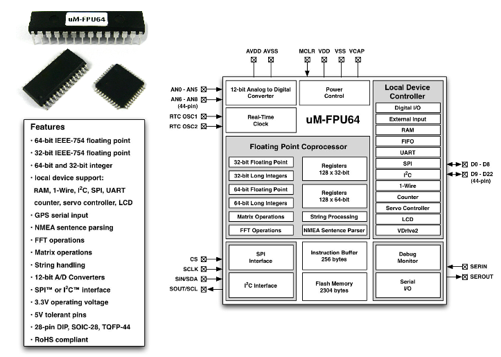
Features
See the uM-FPU64 datasheet for details.
See the uM-FPU64 datasheet for details.
Tuesday, February 7, 2012
WSPR Encoder - Version 1
Updated this posting 8 Feb 2012
I have decided not to release my WSPR encoder for Propeller on the Object Exchange at the Parallax web site and instead I created a Github project repository for it. I am releasing it free of charge under the same MIT License that is used at the Object Exchange however.
You can obtain the files at https://github.com/ko7m/WSPR. Looking at this web page, you will see the following:

By clicking on any of the files you can examine them or you can get it all in one go by clicking on "ZIP" near the top and it will bundle up a zip archive and push it down to you.
As always, I welcome feedback or questions. I hope you find it useful.
Monday, February 6, 2012
Another flying diversion
Last week was a total bust for me mostly due to being sick all week. I think I get to blame my grandson for the cold I caught and the associated sinus infection.
Saturday however was one of those phenomenal clear sky, million-mile visibility days with low wind speeds. I decided that if I had to hire someone to fly me, I was going to take to the skies.
Fortunately, a good buddy of mine has a 1948 NAvion L-17-B and had a shout out to anyone wanting to ride along. Sold! My poor little super cub will have to stay in the hanger a little longer until my head is more clear I am afraid.

We left our home field (Harvey Field - S43) in Snohomish, WA and flew to the Olympic Penninsula and cruised the length of Hood Canal stopping for lunch at Shelton (KSHN) at the cafe in the parachute jump centre.

Hood canal runs against the east side of the Olympic Mountains, which I think are particularly beautiful.
.jpg)
.jpg)
After a nice lunch, we decided to head on out to the Pacific Ocean coast and head north. We flew the length of the Washington coast from about Pacific Beach all the way to Neah Bay.
.jpg)
The wind was a bit brisk onshore as evidenced by the breakers on the shallow beach.
.jpg)
We had to circle a few islands off the coast. Pretty rugged coastline with very few options for an emergency landing.
.jpg)
Here we are rounding the bend around Tatoosh Island off Cape Flattery. This is the most north-western point of the United States. I am actually surprised that any of these pictures turned out because as we made this turn, we were just getting slammed around by the wind. Thousands of miles of Pacific Ocean winds from Canada and the Washington coast converging and trying to stuff through the Straits of Juan de Fuca. We picked up a lot of ground speed as we turned east down the Straits.
.jpg)
Looking back south down the Pacific Coast. Sun is dropping towards the horizon.
.jpg)
Crossing Puget Sound from the West, Mt. Rainier in the distance about 10 miles from Harvey Field. On days like this, there is no finer place to fly than the Pacific Northwest.
If you would like to see all of my pictures of the trip, here is a link. About three hours of flying and endless beauty.
Subscribe to:
Posts (Atom)